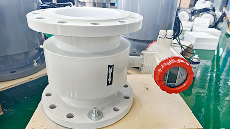
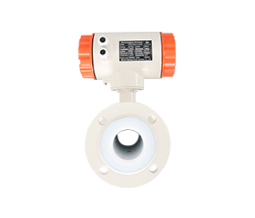
Case
Case

The strength of the induced signal is directly related to the medium's conductivity.
If the conductivity is too low, the generated signal becomes too weak, easily drowned by circuit noise, resulting in a poor Signal-to-Noise Ratio (SNR) and unstable measurements.
Large measurement errors or no signal: Electrodes cannot capture effective voltage when conductivity is below the threshold, causing signal fluctuations or loss.
False alarms or device faults: Built-in self-diagnostics may trigger “empty pipe alarms” or misreport “electrode fouling.”
Long-term instability: Low conductivity fluids tend to form insulating layers (e.g., oxide films) on electrode surfaces, further decreasing sensitivity.
Confirm medium conductivity: Always test the medium’s conductivity before selection, especially considering temperature effects.
Alternative solutions: Use ultrasonic flowmeters (for pure liquids) or Coriolis mass flowmeters (broader application but higher cost) if conductivity is insufficient.
Special treatments: In low-conductivity liquids, electrolytes (e.g., small amounts of salt) can be added to enhance conductivity without affecting the process.
Industry restrictions: Non-conductive media like petroleum, alcohol, and organic liquids must not use electromagnetic flowmeters.
Case 1: A chemical plant attempted to measure deionized water (2 μS/cm) with an electromagnetic flowmeter, resulting in erratic readings. Switching to an ultrasonic flowmeter resolved the issue.
Case 2: A food factory used an electromagnetic flowmeter for vegetable oil transport; due to the insulating nature of the medium, no signal was generated, eventually burning out the converter circuit.
Many users assume electromagnetic flowmeters can adapt to any pipe size or flow condition, overlooking the critical matching requirements for pipe diameter and flow range.
Low flow measurement failure:
Example: DN300 pipe with flow velocity at only 0.1 m/s, using a flowmeter rated for 0.3–10 m/s. The result: no stable output.
Device damage at high flow velocities:
Example: DN50 pipe with flow velocity reaching 15 m/s, causing long-term liner peeling and electrode corrosion.
Flow profile distortion due to size mismatch:
Example: Installing a DN150 flowmeter on a DN200 pipe without proper transitions leads to turbulent flow and significant reading errors (up to ±10%).
Strictly match flow velocity range:
General liquids: 0.5–5 m/s
Crystallizing/particle-containing media: ≥1 m/s
Low-velocity optimization models are needed for velocities around 0.1 m/s.
Pipe size adaptation and flow optimization:
Match meter bore with pipeline diameter.
Straight pipe runs: ≥5D upstream, ≥3D downstream (D = pipe diameter).
If necessary to reduce diameter, use gradual reducers (maximum 1.5:1 ratio).
Case 1: A sewage plant installed an electromagnetic flowmeter in a DN400 rainwater pipe; during dry seasons, flow velocity dropped below 0.2 m/s, causing signal loss. Switching to a multi-channel ultrasonic flowmeter solved the problem.
Case 2: A chemical plant transporting concentrated sulfuric acid at 12 m/s using a non-high-speed resistant liner (rubber) experienced liner failure and acid leakage within three months.

Industry Reality: Over 80% of liner failures are caused by exceeding temperature or pressure limits.
| Liner Material | Maximum Temperature | Pressure Resistance | Suitable Media |
| PTFE | 180°C | 1.6 MPa | Strong corrosives |
| Rubber | 80°C | 4.0 MPa | Neutral liquids |
| PFA | 200°C | 2.5 MPa | Food-grade applications |
Emergency Measures: Install heat exchangers or cooling jackets for overheated conditions.
Fatal Mistake: Insufficient straight pipe runs leading to flow profile distortion.
Installation Guidelines
Upstream straight pipe ≥5D
Downstream straight pipe ≥3D
Never install within 3D downstream of a pump outlet.
Case Study: A hydroelectric station experienced a 7.8% periodic fluctuation due to insufficient installation distance.
Chemical Corrosion Impact: Electrode material failure accounts for 27% of faults annually.
Quick Selection Guide
316L Stainless Steel: General acid/base solutions (pH 2–10)
Hastelloy C: Concentrated sulfuric or hydrochloric acids
Titanium Alloy: Seawater, chlor-alkali industries
Tantalum Electrodes: High-temperature concentrated sulfuric acid, hydrofluoric acid
Measurement Black Hole: One hour of empty pipe operation can cause electrode damage exceeding $1,500.
Preventive Measures
Equip with standard empty pipe detection (verify output signal type).
For vertical installations, ensure flow direction is bottom-up.
Install automatic air vents at pipeline high points.
Electrical Trap: Mixing 24VDC and 220VAC supply types causes a 17% early failure rate.
| Power Supply | Output Signal | Transmission Distance | Suitable Scenarios |
| 24VDC | 4-20mA + HART | ≤500m | Explosion-proof zones |
| 220VAC | Pulse + RS485 | ≤100m | Fixed installations |
Cost Trap: 0.2% accuracy devices cost 3–5 times more than 0.5% ones.
Accuracy Selection Formula:
Required Accuracy = (Process Tolerance × 0.6) / Flowmeter Range Ratio
Typical Examples
Municipal water supply: 0.5% is sufficient.
Pharmaceutical ultrapure water: 0.2% is necessary.
Invisible Killer: Poor grounding accounts for 42% of random errors (Data source: Endress+Hauser report).
Triple Grounding Rules
Connect sensor and pipeline with ≥4mm² copper wire.
Independent grounding with resistance <4Ω.
Avoid sharing grounding points with motors.